Steel Reinforcement in Shop Drawings: Why is there still steel wastage despite accurate statistics?
Accurate drawings, complete statistics, but actual materials still incur waste? Find out the causes and ways to optimize reinforcement layout to control materials more effectively during the Shop Drawing process for reinforcement.
During the Shop Drawing process, engineers often spend a lot of time checking the length, quantity, and volume of reinforcement steel to ensure the documentation is accurate before fabrication.
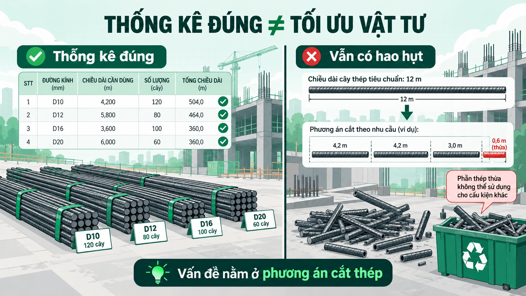
However, there is a situation that is not uncommon: The reinforcement statistics table is correct, and the quantities and lengths match the drawings, but during actual fabrication, the amount of steel used is still higher than expected.
The cause does not necessarily lie in wrong statistics. Sometimes, the problem comes from how to arrange steel cutting plans, utilize excess steel and manage materials during construction.
This is also the reason reinforcement detailing in Shop Drawing plays an important role, helping to connect drawing data with machining plans and actual material usage.

1. Why can waste still occur even when reinforcement steel is calculated correctly?
The reinforcement bar schedule is an important part of the Shop Drawing documentation, showing information such as diameter, shape, length, quantity, and the volume of steel required for each component.
When the statistics table is accurate, engineers can determine the reinforcement requirements according to the design. However, Knowing how much steel is needed does not mean that the most efficient way to use the steel has been determined.
In practice, steel is supplied in certain commercial lengths, such as 11.7m long steel bars. Meanwhile, the length of the steel bars requiring fabrication depends on the size, shape, and structural requirements of each component.
When cutting rebar into segments of different lengths, the remaining material can either be reused or become scrap if it does not fit subsequent fabrication requirements.
Therefore, a set of records with accurate statistical volumes may still incur losses during the processing process if the steel cutting plan is not optimized.
In other words, reinforcement statistics help determine material requirements, while reinforcement detailing helps find ways to meet those requirements with more optimal steel usage plans.
2. What is reinforcement detailing in Shop Drawings?
Steel cutting optimization is the process of selecting and arranging the required steel segments to be processed from raw steel bars of specific lengths, in order to maximize material utilization and minimize unusable scrap steel.
Instead of just considering each individual steel bar, the steel mixing process poses an overall problem: Which steel sections can be combined on the same raw steel bar to minimize waste while still meeting technical requirements?
For example, with a steel bar 11.7m long, the engineer can consider many different cutting options depending on the list of steel lengths that need to be processed.
An efficient reinforcement detailing plan needs to simultaneously consider the length of the cut segments, quantity, diameter, material type, current stock levels, and the ability to utilize offcuts.
It is important that material optimization is not achieved by arbitrarily changing the anchorage length, lap length, or approved structural requirements.
In practice, the option with the shortest remnant may not necessarily be the most suitable if it is difficult to organize processing, incompatible with inventory, or fails to meet technical constraints.
3. Common causes of steel cutting waste
3.1. Cutting steel by group without considering the common coordination plan
During the machining process, if each group of steel lengths is processed independently, the remaining steel after cutting may not be utilized for other groups.
For example, after cutting a long piece of steel, the remainder may still be sufficient to machine a shorter piece. However, if the steel groups are not cross-referenced and organized within the same plan, this opportunity for utilization is easily overlooked.
As the number of components and types of steel increase, determining an optimal coordination plan through mental calculation or manual checking also becomes more complex.
3.2. Surplus steel inventory has not been well controlled
Not every piece of steel remaining after processing is scrap.
Some remaining steel sections still meet the requirements for length, diameter, type, and quality to be continued for use in appropriate items.
However, without clear information regarding the quantity, length, and condition of the leftover steel pieces, the fabrication department may continue to use full-length steel bars for requirements that could have utilized existing materials.
This not only affects the efficiency of steel usage but also makes inventory control difficult.
3.3. Drawings have changed but the steel cutting plan has not been updated
For construction projects, design adjustments or changes to component details may occur during implementation.
When the length or quantity of reinforcement changes, the summary table and reinforcement layout must also be reviewed accordingly.
If data is not updated synchronously, the old steel cutting plan may no longer suit actual needs, leading to excess materials or additional processing.
3.4. Drawing, statistical and steel warehouse data have not been linked
Another difficulty is that the information for processing may be located in various sources: CAD drawings, Excel statistics tables, inventory material lists, and processing plans.
When having to constantly transfer, reconcile, or manually update data between sources, engineers can easily spend more time checking, especially when there are numerous record adjustments.
3.5. Only focusing on the amount of surplus steel while ignoring the construction conditions
A reinforcement layout with a low waste rate is a point of interest, but it is not the sole criterion.
Factors such as design requirements, actual cutting length, processing organization, steel grade, and the usability of remnants all need to be considered.
The goal is not to cut the rebar as close to length as possible, but to find a suitable balance between material efficiency, technical requirements, and construction conditions.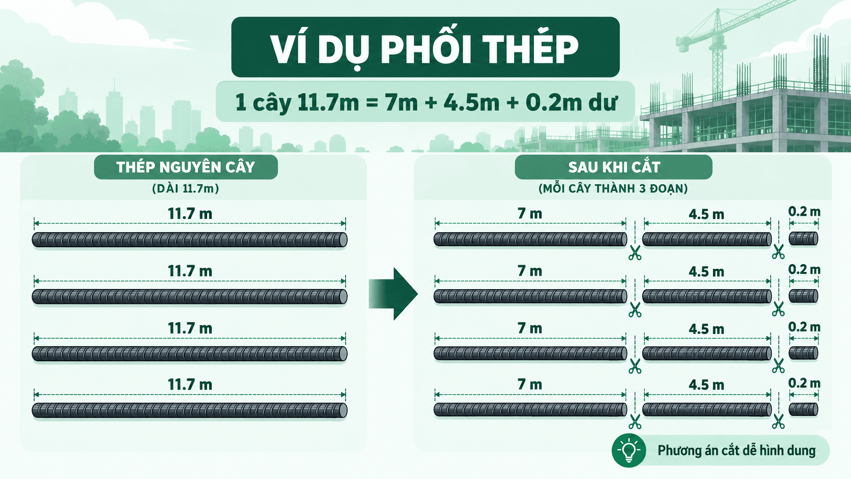
4. Example: For the same amount of steel to be processed, how does the coordination plan affect the waste?
To make it easier to visualize, let's consider a simple example.
Assume an item requires the machining of 8 steel sections of the same diameter and type, including:
4 steel sections 7m long.
4 steel sections 4.5m long.
The total length of the finished steel to be used is:
(4 × 7) + (4 × 4.5) = 46m.
Input materials are raw steel bars with a length of 11.7m.
If considering each length independently and not utilizing the leftover steel, the quantity of steel bars used may be greater than necessary.
Conversely, when combining a 7m section with a 4.5m section on the same steel bar, we have:
7m + 4.5m = 11.5m.
Thus, for each 11.7m steel bar, the remaining part according to theoretical calculation is:
11.7m – 11.5m = 0.2m.
Applying this method to 4 steel bars, the total input material length is 46.8m, which sufficiently meets the demand for 46m of finished products.
The remaining theoretical length is 0.8m, equivalent to approximately 1.71% of the total input steel length.
Note: Examples only illustrate the principles of reinforcement steel layout along the length; they do not account for losses due to cutting, machining tolerances, and other technical constraints. Surplus sections are not automatically considered scrap if they can still be reused.
The actual problem will be much more complicated when the number of steel bars increases, different diameters, shapes, and lengths appear and the amount of steel inventory must be considered.
However, the above example demonstrates an important point: With the same need for reinforcement, the way the processing plan is arranged can make a difference in the efficiency of material use.

5. How to optimize reinforcement detailing during the Shop Drawing process?
Step 1. Normalize the rebar data to be processed
Before arranging the reinforcement steel, the engineer needs complete data on the diameter, type, shape, cutting length, and quantity of the steel bars.
This information needs to be checked according to the drawings and technical requirements of the project.
The clearer the input data, the more favorable the reinforcement planning and result control.
Step 2. Check raw steel and inventory levels
Instead of relying solely on the list of steel to be processed, the actual amount of materials on hand should also be cross-referenced.
In particular, leftover steel segments that can be reused must be clearly managed by length, diameter, type, and material condition.
Keeping track of inventory helps avoid overlooking available materials that could be utilized in the next processing plan.
Step 3. Develop and compare reinforcement options
With the same list of steel to be processed, engineers can consider multiple combinations of cutting segments on the raw steel.
The comparison process focuses not only on the remaining length but also needs to evaluate the quantity of rebars used, the efficiency of material utilization, and the compatibility with the fabrication organization.
This is a stage that can become time-consuming if the quantity and length of steel to be processed are too large.
Step 4. Check the design before sending it for processing
After selecting the coordination option, it is necessary to cross-check it with the design data and actual conditions.
In particular, do not arbitrarily change the anchorage length, lap length, or structural parameters solely to reduce steel waste.
Material optimization is only truly meaningful when the quality and technical requirements of the project are still ensured.
Step 5. Update results and manage materials after processing
After implementing the steel cutting plan, the amount of materials used and the remaining steel segments must be recorded.
This helps the technical and materials management departments have data for cross-checking, limiting discrepancies between the plan and reality, and supporting subsequent machining batches.

6. Software application to support steel reinforcement design and steel inventory management
For items with a large quantity of reinforcement steel, creating and comparing manual cutting and bending plans can be significantly time-consuming.
Engineers not only need to calculate how to combine steel sections but also must track inventory, verify data, and update plans when changes occur.
This is where reinforcement support tools prove their value, helping to reduce repetitive tasks and supporting engineers in choosing more appropriate options.
TakaCAD – Supporting reinforcement detailing and steel inventory management in the Shop Drawing process
TakaCAD is software that supports the implementation of reinforcement Shop Drawings, developed to help engineers improve work efficiency from data processing and component deployment to statistics.
In addition to the reinforcement deployment tools for Beams, Slabs, Columns/Walls, Foundations, and Stairs, TakaCAD also provides the function Steel Reinforcement & Steel Inventory Management, supporting engineers in developing material usage plans.
With this functional group, users can:
Enter the steel data to be coordinated: Receive information from Excel or directly from the CAD environment.
Select reinforcement option: Consider the option based on the loss rate, inventory status, and priority levels.
Steel warehouse management: Update reinforcement results in the warehouse data for convenient tracking.
Check logs: Track information and processing history for control purposes.
Instead of having to completely separate drawing data, schedules, and the reinforcement process, engineers now have tools to help link these stages during implementation.
As a result, reinforcement detailing is not limited to calculating cutting lengths but also aims toward more systematic material management and utilization.
Of course, the results from the software still need to be verified by engineers according to the design requirements, machining conditions, and the actual construction of each project.
7. Frequently Asked Questions about reinforcement detailing in Shop Drawings
Are steel reinforcement detailing and reinforcement scheduling the same?
Not entirely. Rebar statistics focus on determining the quantity, length, shape, and mass of steel according to the drawings. Meanwhile, rebar cutting optimization focuses on how to arrange the steel segments to be processed on the input material source to improve utilization efficiency.
Is all remaining steel after cutting considered scrap?
No. Surplus steel sections that still meet technical specifications and can continue to be used must be distinguished from scrap that can no longer be utilized. The classification and management of surplus materials are key factors in controlling wastage.
Should the length of the reinforcement steel be changed to optimize the steel arrangement?
Do not arbitrarily change the approved structural parameters. All adjustments related to anchorage length, splicing, or reinforcement layout must meet design requirements and be reviewed according to the project's technical procedures.
8. Conclusion: Accurate statistics are not enough; the steel utilization plan must also be optimized.
In the implementation of reinforcement Shop Drawings, an accurate summary table is a critical basis for controlling material quantities. However, the efficiency of steel usage also depends on the cutting plan, the ability to utilize scrap steel, and the inventory management process.
Effective steel reinforcement optimization is not simply about finding ways to reduce scrap length, but also about connecting the requirements from drawings with the actual fabrication and material utilization plans.
With the support of specialized tools such as TakaCAD, engineers can step-by-step optimize the process from drawing deployment and reinforcement statistics to steel detailing and inventory management, while reducing manual calculation and verification tasks.
Experience TakaCAD to discover a faster, more convenient, and more efficient process for deploying reinforcement Shop Drawings.
Please provide the text you would like me to translate. Try TakaCAD free for 30 days
🌐 Website: takacad.com
📞 Support Hotline/Zalo: 0356 719 001