Rebar splicing in construction: Distinguishing between lap splicing and mechanical splicing and notes for Shop Drawing implementation
In reinforced concrete construction, a steel bar cannot always extend continuously along the entire length of a component. Limitations in commercial steel lengths, as well as transportation, fabrication, and installation conditions, make it reinforcing steel splicing become a familiar process at the construction site.
However, splicing steel is not simply joining two steel bars together. The splicing location, splice length, and connection method all affect the force transmission capacity, reinforcement layout, and construction feasibility.
Two common methods are rebar lap splice and mechanical splicing using couplersSo, how do they differ, in which cases should they be used, and what should engineers keep in mind when implementing Shop Drawings?
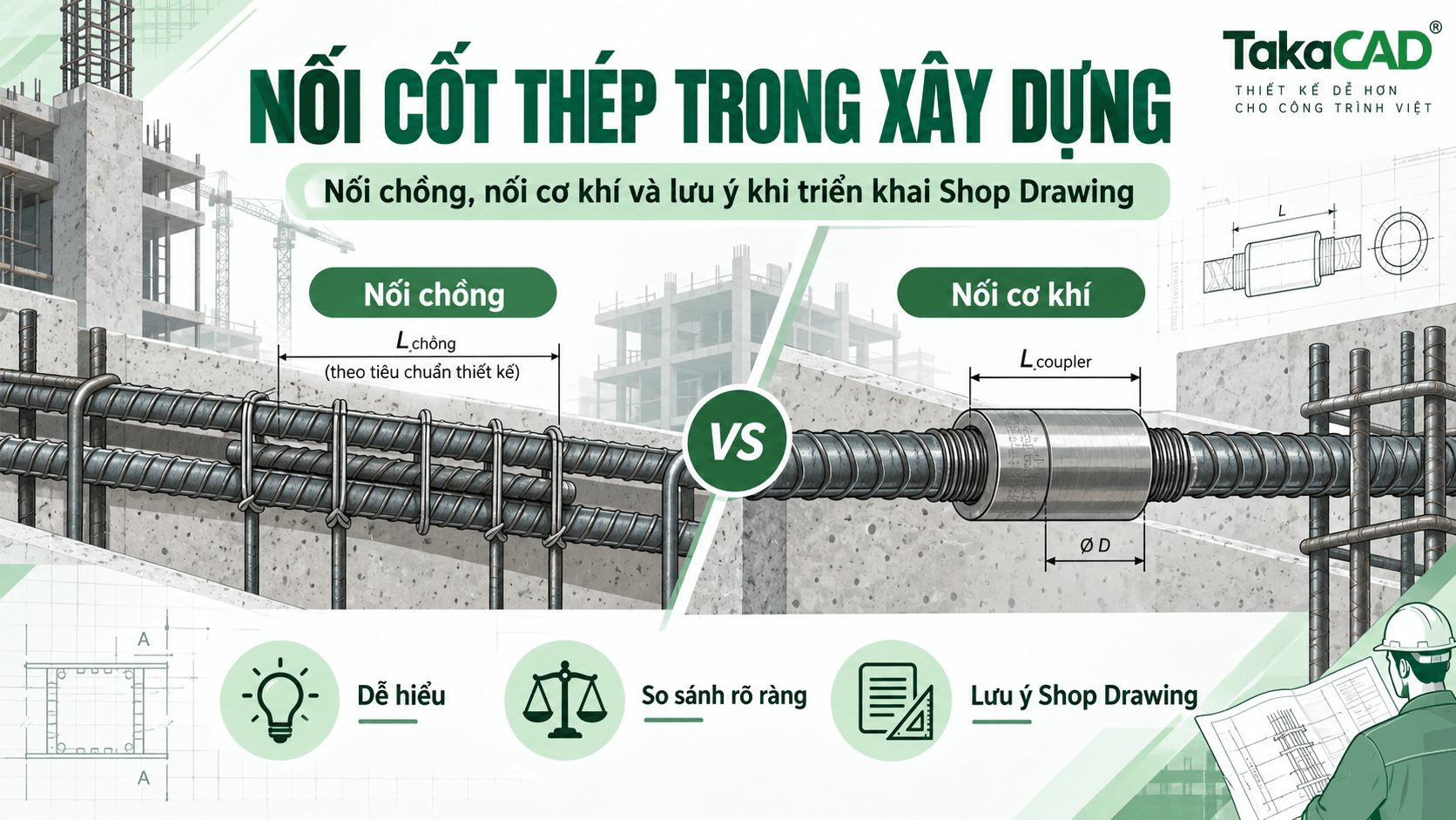
1. What is rebar splicing? Why is it necessary to splice steel in construction?
Reinforcement splicing is a method of connecting reinforcing bars to ensure the required force transmission capacity according to the design at locations where a continuous steel bar is not used.
In practice, steel splicing usually stems from many causes:
Commercial steel length limits: Not every component can use a single full-length steel bar.
Shipping and installation conditions: Steel bars that are too long can cause difficulties during transportation, lifting, or arrangement.
Construction characteristics by phase: Some structures require the placement of starter bars for splicing in subsequent construction phases.
Structural configuration requirements: The position and connection method are selected to meet the load-bearing and construction conditions of each component.
Regardless of the method used, the joints must meet the technical requirements according to the design documents and applicable standards.
2. Rebar splicing – A common method in construction
2.1. What is reinforcement lap splicing?
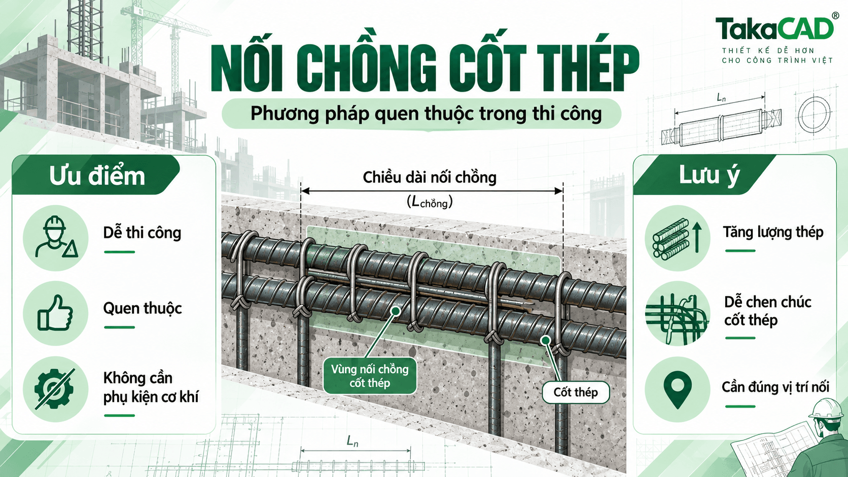
Reinforcement Lap Splice is the method of overlapping two steel bars over a specified length.
For non-welded lap splices, the force is transmitted between the steel bars through the action of the reinforcement and the surrounding concrete, primarily due to the bond strength.
Steel bars may be tied to maintain their correct position during installation and concrete pouring. However, the tie wires are not the components directly responsible for the design load-transfer capacity of the joint.
2.2. Advantages of reinforcing bar overlapping
Overlapping is commonly used because this method is relatively simple and familiar to many construction teams.
Outstanding advantages:
No need to use specialized mechanical couplings.
No special thread machining equipment is required for conventional joints.
Convenient for fabrication and installation when components have sufficient space for reinforcement placement.
It can be applied to various types of components such as beams, slabs, columns, or walls when design requirements are met.
2.3. Limitations of the overlapping method
Besides the advantage of simplicity, stacking also has limitations that need to be considered.
First, it increases the length and volume of steel used. Since the two bars must overlap by a certain length, the total length of the fabricated steel may increase compared to the butt joint method.
Secondly, it is easy to cause reinforcement congestion. In areas with high reinforcement density, adding lap splices can narrow the space between bars, causing difficulties during installation and concrete pouring.
Third, the location and length of the joints need to be strictly controlled. If the arrangement does not meet the requirements, the joint may not guarantee the operational capacity as intended in the design.
Therefore, although it is a familiar method, the overlap still needs to be calculated and clearly shown on the drawing.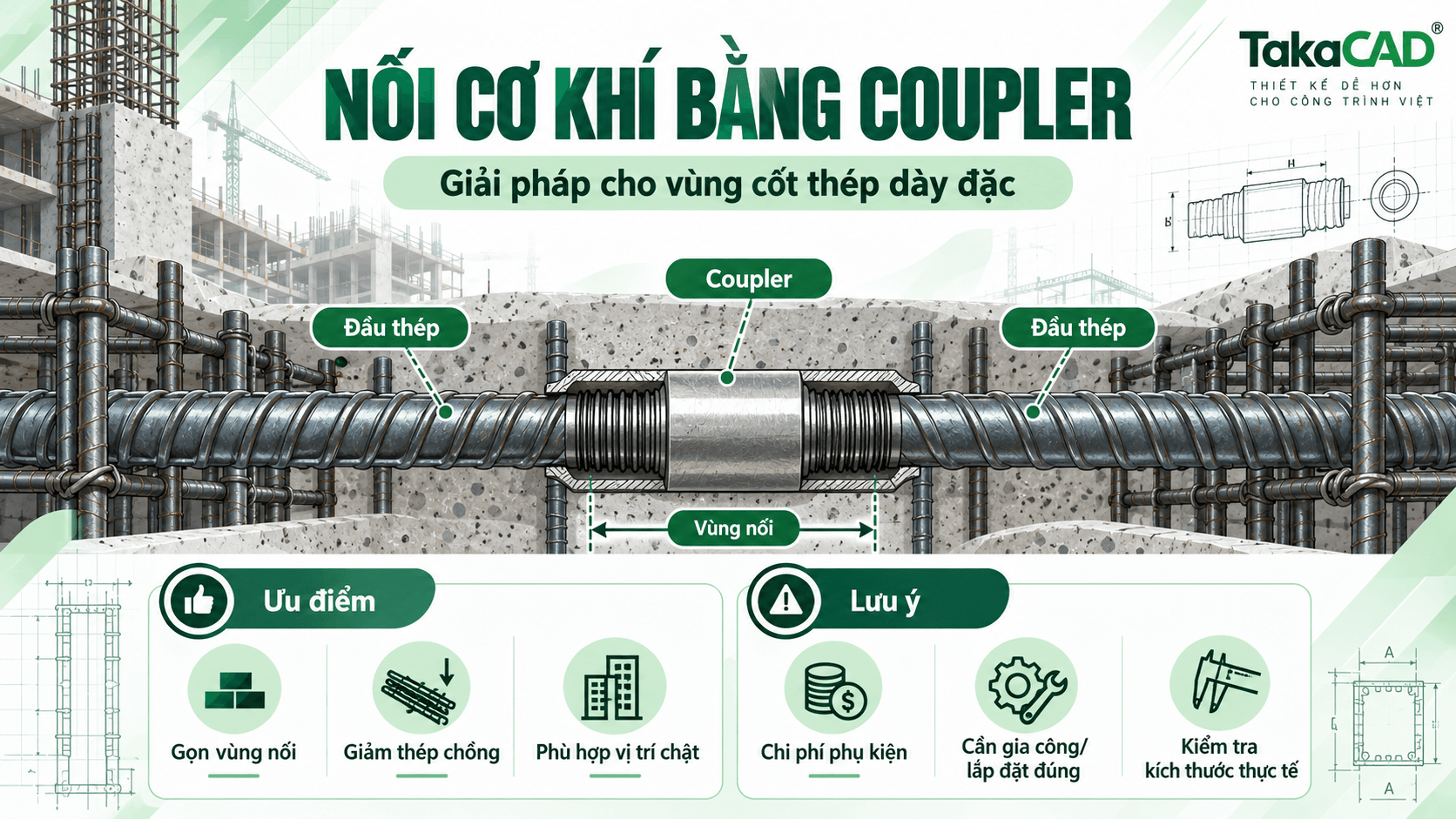
3. Mechanical splicing with couplers – A solution for densely reinforced areas
3.1. What is mechanical splicing of reinforcement bars?
Mechanical Splice is a method that uses specialized connecting components to join two steel bars and transmit force through a mechanical coupling mechanism.
Some common types of mechanical joints include:
Connect threads using a steel coupler.
Connect using crimped tubes.
Other specialized mechanical splicing systems are designed to suit the requirements of the project.
Among these, threaded connection using a coupler is the form most well-known to engineers.
Instead of arranging two bars to overlap for a long section, the two ends of the steel bars are connected via a suitably designed coupler.
3.2. Advantages of mechanical splicing
Reduce the amount of overlapping steel: The butt-joint method does not require lap lengths like traditional splicing, thereby potentially reducing the amount of steel used at the connection area.
Reduce reinforcement congestion: Particularly useful when needing to consider connection options at components with high steel density.
Convenient for certain construction conditions: Suitable coupler systems can support steel splicing in cases where length and installation space are limited.
However, the actual effectiveness also depends on the type of coupling, steel diameter, detailed design, and construction conditions.
3.3. Limitations to note
Mechanical connection is not always the optimal solution.
This method often incurs additional costs for connecting materials, steel end processing, quality inspections, and technical requirements during installation.
In particular, connectors with an outer diameter larger than the steel bar may affect the clear spacing, the concrete cover, and the arrangement of adjacent steel bars.
Therefore, it is necessary to select a jointing system that meets the design requirements, applicable standards, and the manufacturer's technical procedures.
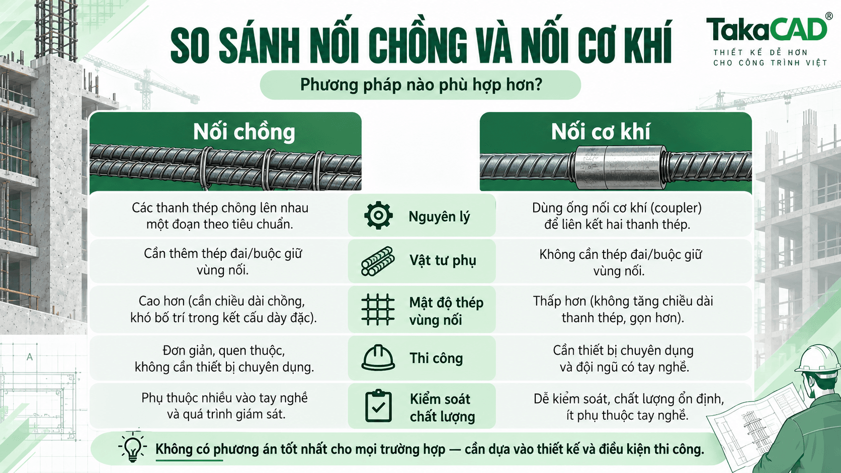
4. Comparing lap joints and mechanical joints: Which method is more suitable?
| Criteria | Stacking | Mechanical connection |
|---|---|---|
| Principle | Overlap two bars on a specific segment | Connected by specialized mechanical details |
| Accessories | Mainly fixed installation materials | Connecting pipe or corresponding accessories required |
| Amount of steel at the connection zone | Additional steel overlap section | No need for long paragraphs |
| Construction | Relatively familiar | Must meet processing and installation requirements |
| Thick steel area | May cause crowding | Steel overlap can be reduced, but the size of the coupling must be checked. |
| Quality Control | Length, position, distance and structure | Type, joint quality, installation, and location |
So which method should be chosen?
If the component has sufficient layout space, appropriate load-bearing conditions, and the design documents allow it, lap splicing can be a simple and convenient option.
Conversely, in locations with high steel density or where overlapping steel bars need to be limited, mechanical splicing can provide clear benefits.
It is important that no single reinforcement splicing method is always better in every caseThe selection should be based on the approved design plan, construction conditions, and overall economic efficiency.
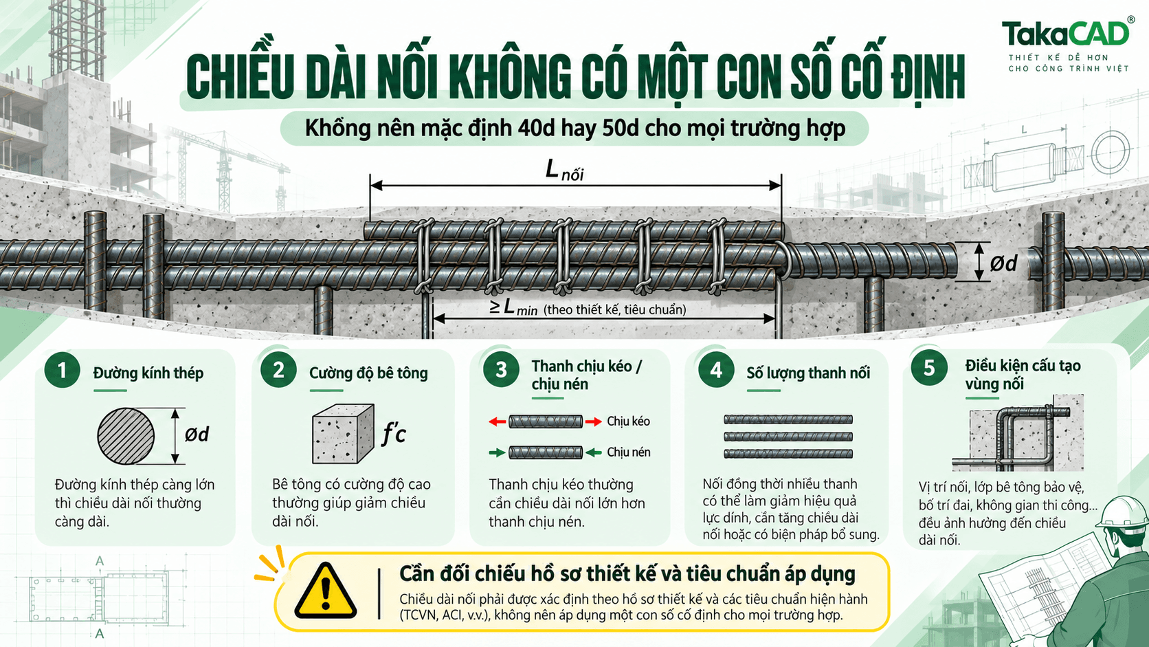
5. What is the correct length for rebar lap splicing?
When researching reinforcement splicing, many engineers often encounter quick calculation methods such as 40d or 50d, in which d is the diameter of the steel bar.
However, It cannot be assumed by default that all overlap cases use the same multiplier for the steel diameter.Please provide the text you would like me to translate.
According to TCVN 5574:2018, section 10.3.6 regarding the splicing of non-prestressed reinforcement, the lap splice length is determined based on various factors, including material properties, loading conditions, and the structural conditions of the splice zone.
Factors to consider include:
Diameter and mechanical properties of reinforcing steel.
Strength and characteristics of concrete.
Tension or compression state of the steel bar.
The number of bars spliced within the same calculation cross-section.
The spacing between bars and the construction conditions at the splice zone.
TCVN 5574:2018 also stipulates the use of non-welded lap splices for reinforcing bars with a diameter not exceeding 40 mm, while simultaneously satisfying structural requirements and relevant splice lengths.
Therefore, when implementing Shop Drawings, engineers need to prioritize the details and reinforcement splicing instructions in the approved design documents, combined with checks according to the applicable project standards.
A fixed splice length should not be arbitrarily applied to the entire component without first verifying the design conditions.
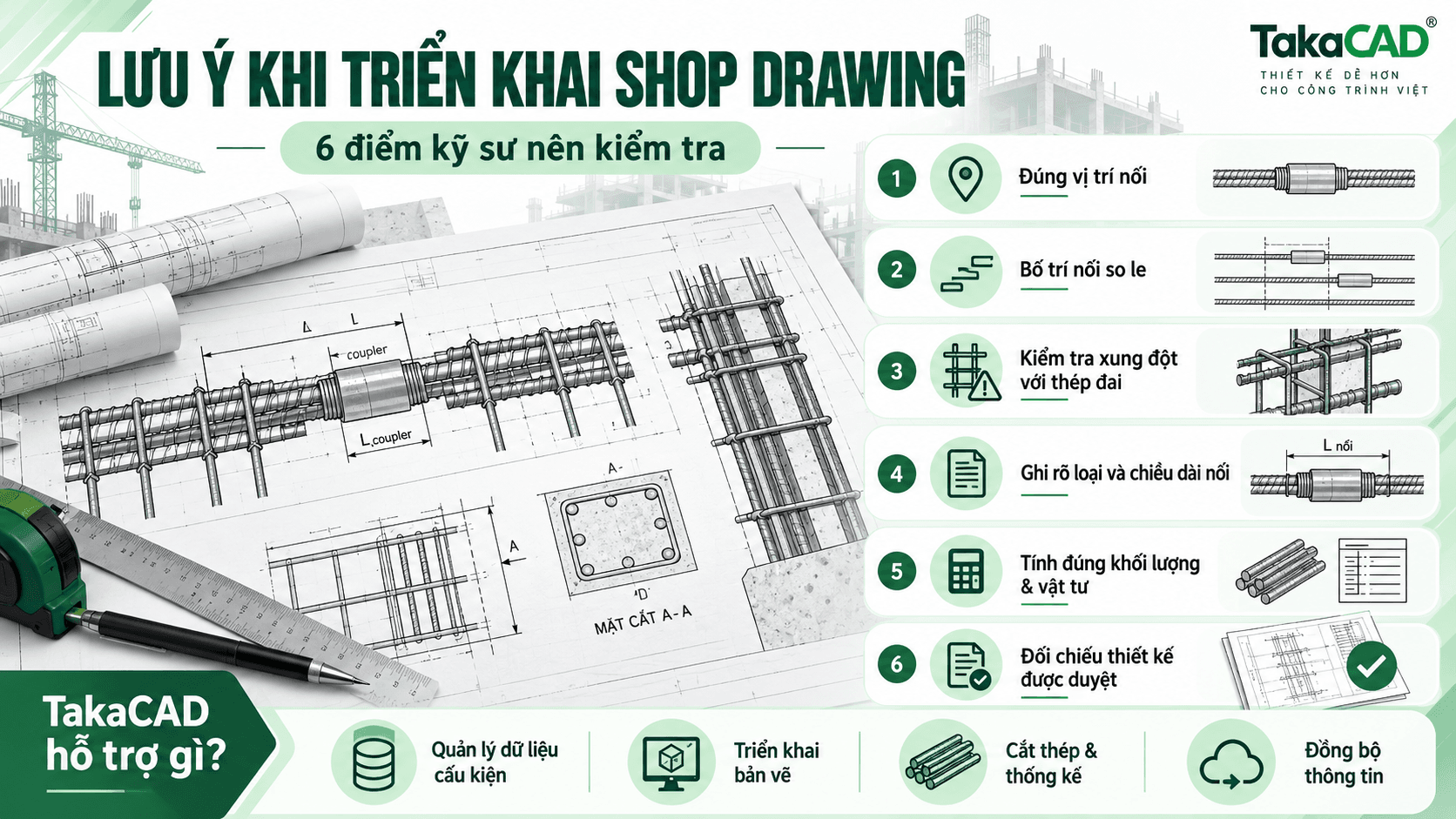
6. Important notes when implementing reinforcement splicing on Shop Drawings
A theoretically reasonable steel reinforcement splicing plan may still encounter difficulties during site implementation if the information on the shop drawings is not clear.
Here are 6 points that engineers need to pay attention to.
6.1. Correctly determine the steel splicing positions
Not every position on beams, columns, slabs, or walls can be arbitrarily arranged for joints.
The connection positions must be determined based on the structural diagrams, construction requirements, and instructions of the design documentation.
During implementation, engineers must clearly distinguish between different load-bearing zones and must not arbitrarily move joints for the sake of convenience in dividing steel bar lengths.
6.2. Control of staggered joint layout
In components with many longitudinal steel bars, arranging all joints at the same location may affect the load-bearing requirements or cause difficulties during construction.
Depending on the design, joints may need to be staggered to meet the limit on the number of splicing bars in a calculation section.
Engineers must clearly indicate the position of each rebar group, rather than just specifying a general lap length and leaving the arrangement to the construction team.
6.3. Check for conflicts with stirrups and structural steel
The intersection between beams and columns, areas with dense reinforcement, or components with multiple layers of steel often harbor potential risks of conflicts during installation.
Especially for mechanical splicing, it is necessary to check the actual dimensions of the coupling instead of only considering the nominal diameter of the steel bar.
This is an important step to ensure the clear span, concrete cover, and concrete pouring conditions.
6.4. Fully display joint information
Shop Drawings must provide sufficient information for the construction team to identify and correctly implement the connection method.
Depending on the case, information may include the type of joint, location, lap length, type of connector, steel diameter, and related structural details.
This information must be consistent across floor plans, sections, detailed drawings, and technical notes.
6.5. Correctly calculate the weight of steel and connection materials
The connection method directly affects the fabrication process and material statistics.
For lap splicing, the actual length of the bars must reflect the steel lap length according to the approved method.
For mechanical splices, in addition to the quantity and length of the steel bars, the quantity and type of couplers as well as related fabrication requirements must be separately listed.
Deviations at this step can lead to material shortages, incorrect fabrication lengths, or the need for adjustments at the construction site.
6.6. Compare the shop drawings with the approved design
Before issuing Shop Drawings, engineers must check the consistency between design drawings, construction notes, detailed drawings, and schedules.
If adjustments to the connection method compared to the design are required, the changes must be reviewed and approved according to the project's technical procedures before implementation.
7. How to implement reinforcement shop drawings more effectively?
In addition to understanding steel splicing methods, engineers must also handle various related steps: reading design drawings, managing component parameters, bar cutting, detailed deployment, and quantity takeoff.
When the volume of drawings is large, managing distributed data or manual editing can easily lead to a lack of synchronization between the drawings and the schedules.
This is also why tools that support Shop Drawing implementation are receiving increasing attention.
TakaCAD – Supporting the deployment and management of reinforcement drawings
TakaCAD is software that supports the deployment of reinforcement Shop Drawings on a CAD platform, developed to meet the practical working needs of civil engineers.
The software supports the deployment of components such as Beams, Slabs, Columns/Walls, Foundations, and Stairs, with the following utilities:
Component data management: Centralize information for convenient checking and updating.
Drawing deployment support: Reduce repetitive tasks during the reinforcement detailing process.
Steel cutting and statistics: Supports managing the length, quantity, and volume of reinforcement steel.
Data synchronization: Limit the inconsistency of information between stages.
The selection of the connection method and the verification of technical requirements must still be performed by the engineer in accordance with the approved design documents.
Instead of spending too much time on repetitive CAD tasks, engineers can focus more on checking the structure, installation feasibility, and the quality of the detailed design documentation.
Explore TakaCAD and experience the reinforcement Shop Drawing software at:
Please provide the text you would like me to translate. https://takacad.com/vi
Consulting support: 0356 719 001
8. Conclusion
Lapping and mechanical splicing both play important roles in the construction of reinforced concrete structures. Each method has its own principles, advantages, and application conditions.
While lap splicing is prominent for its simplicity and familiarity in construction, mechanical splicing offers a useful alternative when it is necessary to limit the amount of lap steel or handle areas with high reinforcement density.
Regardless of the chosen method, the importance lies not only in how the two steel bars are joined, but also in the correctly determine the position, meet the load-bearing requirements, and fully present information on the Shop DrawingsPlease provide the text you would like me to translate.
A good shop drawing needs to be more than just design-accurate; it must also be clear, easy to verify, and convenient for the construction team to execute on-site.