Concrete cover for reinforcement: Why can shop drawings be wrong even with the correct dimensions?
Not only is it the distance between the reinforcement and the concrete edge, but the concrete cover also affects the structural durability and the accuracy of the Shop Drawings.
A Shop Drawing may have full dimensions for beams, columns, slabs, and foundations, and the amount of reinforcement may match the design. However, when checking details or implementing them at the construction site, the drawing may still require adjustments.
The cause sometimes comes from a seemingly very small parameter: concrete cover thickness for reinforcementPlease provide the text you would like me to translate.
Simply misidentifying the measurement location, ignoring the stirrup diameter, or applying the same cover value to multiple components can make the reinforcement layout on the drawing no longer comply with the design requirements.
So, what is concrete cover, how is it regulated, and what should Shop Drawing engineers keep in mind during implementation?
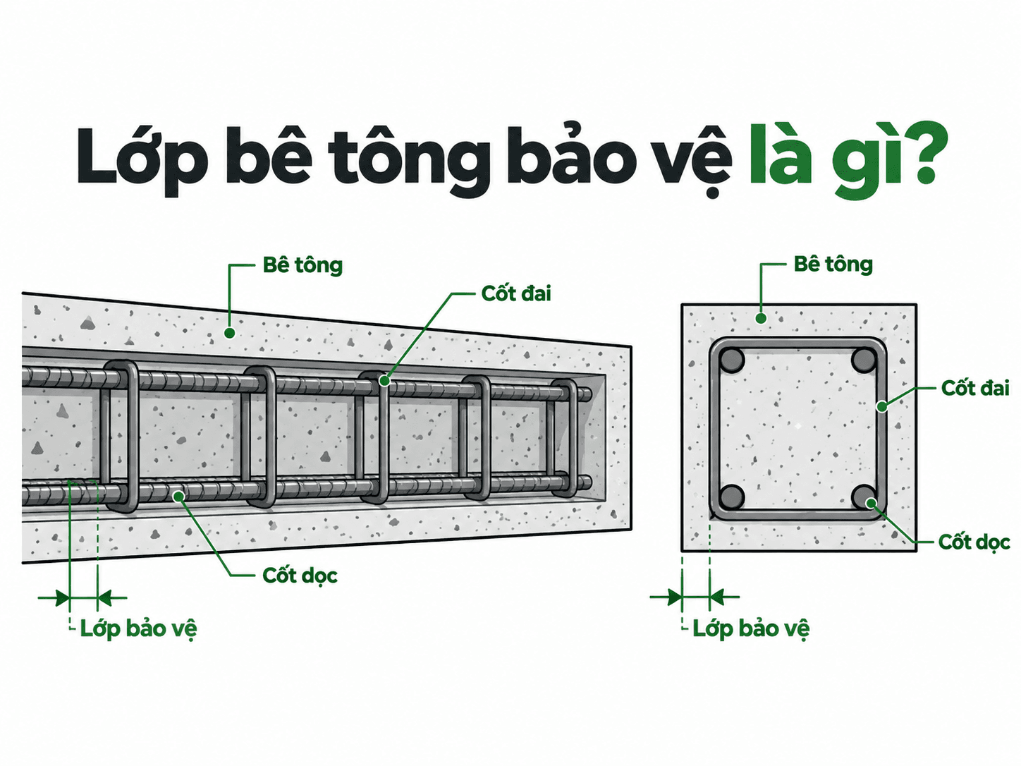
1. What is concrete cover for reinforcement?
Concrete cover is the part of the concrete located between the outer surface of the structural element and the surface of the internal reinforcement.
Simply put, this is the concrete layer surrounding the reinforcement, which helps isolate the reinforcement from adverse effects of the external environment.
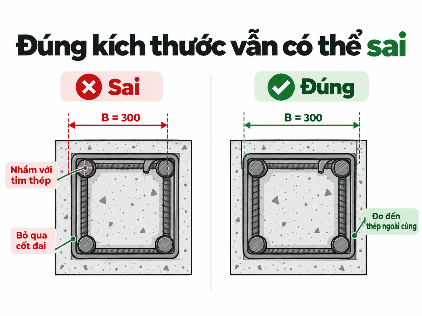
An important point when implementing drawings is the need to distinguish distance to the reinforcement surface and distance to the center of the reinforcementPlease provide the text you would like me to translate.
For example:
For beams and columns, stirrups are usually located outside the longitudinal reinforcement. Therefore, when checking the distance from the concrete edge to the nearest steel bar, the stirrups must also be considered.
For slabs and foundations, it is necessary to correctly identify the outermost steel layer, whether the steel bars are positioned below or above, and the corresponding measurement positions.
For all components, the concrete cover value shown on the Shop Drawing must be correctly understood in accordance with the instructions in the design documents.
Note: Do not assume that all concrete cover dimensions in the drawings are measured to the longitudinal reinforcement. The measurement convention should be clarified before placing the steel.

2. Why is the concrete cover important?
The concrete cover layer is not only significant in geometric terms. According to TCVN 5574:2018, the arrangement of the cover layer must meet requirements related to the structural performance, reinforcement anchorage, environmental impact, and fire resistance.
2.1. Protection of reinforcement against environmental impacts
Concrete creates an alkaline environment that helps limit the corrosion process of reinforcing steel.
When the protective layer does not meet requirements, combined with cracked or honeycombed concrete or adverse environmental conditions, water and corrosive agents can penetrate to the reinforcement.
Over time, corrosion can contribute to cracking, spalling of the concrete, and affect the long-term durability of the structure.
2.2. Ensuring the composite action between concrete and reinforcement
In reinforced concrete structures, two types of materials combine to bear the load.
The protective cover, along with requirements for anchorage, spacing, and reinforcement layout, helps ensure that the structure performs according to the design.
2.3. Contributing to fire resistance requirements
In the event of a fire, the surrounding concrete layer helps slow down the temperature increase of the reinforcing steel.
However, fire resistance requirements are not determined by a single protective layer value. Engineers must still cross-reference the fire prevention and fighting requirements applicable to the project.
2.4. Direct influence on reinforcement layout in drawings
If the concrete cover thickness changes, the position of the reinforcement in the section may also change.
This affects the spacing between bars, the position of stirrups, the layout of multi-layer reinforcement, and the practical constructability.
Therefore, checking the concrete cover is a necessary part of the Shop Drawing implementation process.
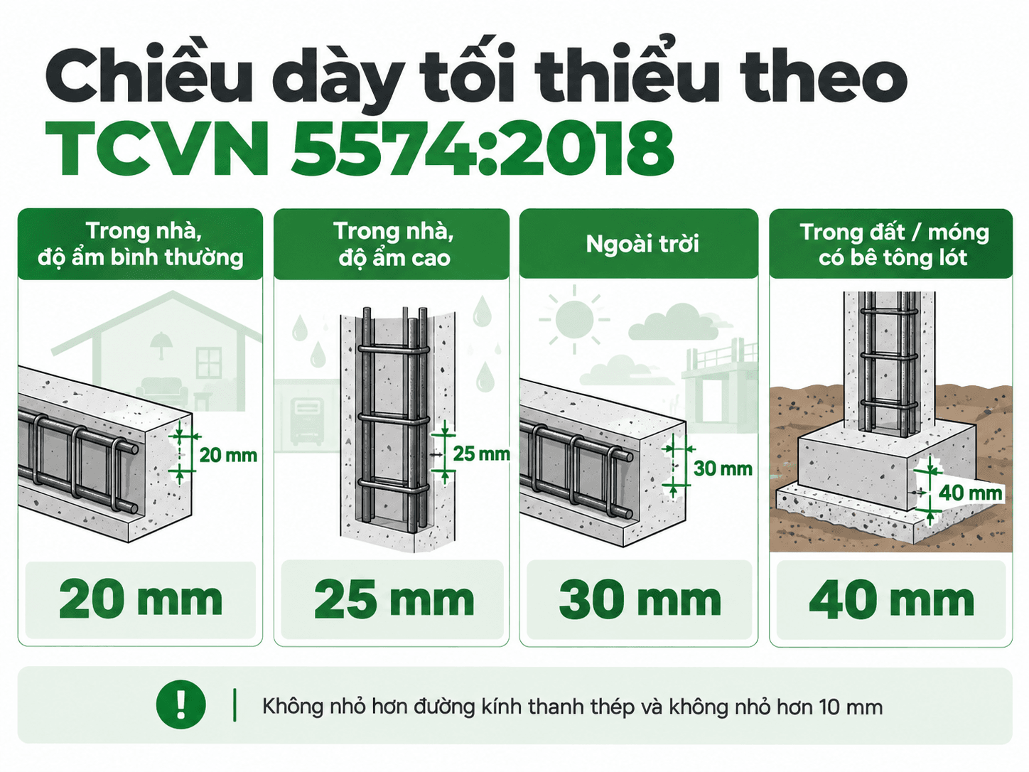
3. Concrete cover thickness according to TCVN 5574:2018
According to section 10.3.1.2 of TCVN 5574:2018, the thickness of the protective layer is determined based on various factors, including the role of the reinforcement, the type of component, the diameter, and the working conditions of the structure.
Table 19 – Minimum concrete cover thickness for reinforcing bars
| Working conditions of the house structure | Minimum thickness |
|---|---|
| In a covered room with normal or low humidity (not exceeding 75%) | 20 mm |
| In a covered room with high humidity (above 75%) and no additional protective measures | 25 mm |
| Outdoors, with no additional protective measures | 30 mm |
| In the soil, there are no additional protection measures; in the foundation, there is a lean concrete layer. | 40 mm |
In addition to the above values, the standard also has requirements to be noted:
First, in all cases, the thickness of the concrete cover shall not be less than the diameter of the reinforcing bar and not less than 10 mm.
Monday, for prefabricated components and constructive reinforcement, the standards have specific regulations on reducing the minimum values compared to the corresponding cases.
Tuesday, when there are additional requirements regarding corrosive environments or fire resistance, relevant standards and regulations must be checked.
The values in the table are the minimum level according to the stated conditions, not the default parameters to be applied to all drawings.
For example, it cannot be concluded that every slab has a 20 mm protective layer or every foundation uses 40 mm without considering the working conditions and design requirements.
In practical implementation, the approved structural records and the standards applied to the project remain the basis for reference.
4. Why can Shop Drawings with correct dimensions still have incorrect concrete cover?
This is a common situation when engineers focus on the overall dimensions without carefully checking the position of each reinforcement layer.
4.1. Confusion between protective cover and distance to the center of the steel bar
Assume a beam cross-section with the following illustrative parameters:
Concrete cover to the outer surface of stirrups: 25 mm.
Stirrup diameter: Ø8.
Longitudinal reinforcement diameter: Ø20.
If the longitudinal steel bar is located close to the straight segment of the stirrup, the distance from the concrete edge to the center of the corresponding longitudinal steel bar is:
25 + 8 + 20/2 = 43 mm.
Thus, in this example, 25 mm is the distance to the outer face of the stirrup, while 43 mm is the distance to the center of the longitudinal reinforcement.
If the two values are confused when constructing the section, the steel may be positioned closer to the concrete surface than expected.
This is a simple geometric example to illustrate how to determine the position of the steel; it is not a design value applicable to all beams.
4.2. Stirrup diameter not considered
On the beam or column cross-section, stirrups usually wrap around the longitudinal reinforcement.
If the position of the longitudinal reinforcement is based only on the protective layer while ignoring the diameter of the stirrups, the actual distance between the steel and the concrete surface may not align with the profiles.
This deviation needs to be noted at the corners of the cross-section, areas with a high density of steel bars, and components with complex stirrup arrangements.
4.3. Using a common concrete cover value for multiple components
A structure may simultaneously contain components that are indoors, outdoors, in contact with soil, or subject to different environmental conditions.
If the same protective layer value is used for all beams, slabs, columns, and foundations without referring to the structural design report, the drawings risk being inconsistent with the design requirements.
4.4. Actual reinforcement layout capability has not been checked
For components with multiple layers of steel or high reinforcement density, ensuring the new cover layer is only part of the problem.
Engineers also need to check the clear distance between bars, the space for concrete filling, and the conditions for construction and concrete compaction.
A cross-section that looks reasonable on CAD may not necessarily be convenient for installation on-site.
5. Key positions to note when implementing Shop Drawings
For beams
The protective layer at the bottom of the beam, both sides of the beam webs, and the top surface must be checked according to the design requirements.
Additionally, attention should be paid to the diameter of the stirrups, the position of the main steel, reinforcement steel, and areas with multiple layers of steel.
For columns and walls
In addition to checking the overall dimensions, engineers need to consider the position of the stirrups, longitudinal reinforcement, and the distance from the outermost steel bars to the concrete surface.
Intersections between columns, walls, and other components must be carefully checked for reinforcement placement feasibility.
For the floor
It is necessary to distinguish between the top reinforcement layer, the bottom reinforcement layer, and the order of the reinforcement directions.
At intersection points, where reinforcement steel is added or the structure is modified, correctly determining the elevation of each steel layer is particularly important.
For foundations
It is necessary to cross-check the soil contact conditions, the lean concrete layer, the distance from the steel to the foundation surface, and the project's design requirements.
At the same time, the positions of the steel layers in each direction, reinforcement bars, and areas intersecting with columns or foundation necks must be checked.
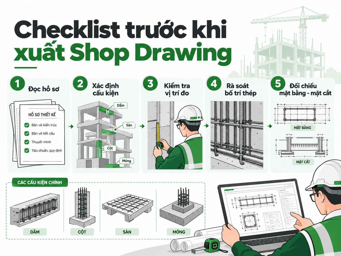
6. Concrete cover checklist before issuing Shop Drawings
To limit errors that require drawing revisions, engineers can establish a 5-step inspection process.
Step 1 – Check the design documents. Identify the concrete cover instructions in the structural descriptions, general notes, and detail drawings.
Step 2 – Component classification. Determine whether the component being implemented is a beam, slab, column, wall, or foundation, and its corresponding working conditions.
Step 3 – Correctly identify the measurement position. Check the distance to the stirrup surface or the outermost steel bar according to the conventions in the documentation, avoiding confusion with the center of the steel.
Step 4 – Check reinforcement layout. Consider the clear spacing, bar diameter, number of steel layers, and positions with high reinforcement density.
Step 5 – Review before publishing drawings. Cross-check floor plans, sections, construction details, and related notes to ensure the represented data is consistent.
A clear inspection process not only helps limit errors but also reduces the need for repeated revisions as drawings pass through multiple departments.
7. Optimizing the reinforcement Shop Drawing process with TakaCAD
In practice, an engineer may have to deploy dozens or even hundreds of components with various cross-sections and parameters.
Reading drawings, entering information, arranging reinforcement, managing components, and manually updating changes can take up a significant amount of time.
TakaCAD is software that supports the deployment of reinforcement Shop Drawings for components such as beams, slabs, columns, foundations, and stairs.
Through the component management and deployment process, engineers can organize their work more conveniently and reduce repetitive tasks during the drafting process.
In particular, the feature View3D allows for observing concrete and reinforcement in 3D directly within the deployment window, supporting visual inspection of reinforcement layout before finalizing the drawings.
However, the determination of the concrete cover layer in accordance with the standards and design records still needs to be checked and confirmed by the engineer.
Want to optimize your Shop Drawing deployment process?
Experience TakaCAD to discover how to manage, deploy, and inspect components more conveniently directly on your actual drawings.
Please provide the text you would like me to translate. Learn about TakaCAD
Please provide the text you would like me to translate. Try for free for 30 days
Conclusion
A shop drawing with correct overall dimensions does not necessarily mean that all reinforcement details have been arranged accurately.
The concrete cover is only a small parameter on the cross-section, but it is directly related to design requirements, the durability of the component, and the feasibility of construction.
Therefore, before exporting the drawing, the engineer needs to double-check carefully concrete cover thickness, reinforcement position, stirrup diameter, and related structural requirementsPlease provide the text you would like me to translate.
Checking accurately against the drawings helps reduce the risk of adjustments when deploying to the site.