Are 2D shop drawings sufficient for checking reinforcement? When is it necessary to view 3D components?
2D Shop Drawings remain the foundation of reinforcement implementation. However, for complex components, incorporating 3D views can help engineers visualize reinforcement layouts more intuitively, identify areas that require inspection, and reduce errors before finalizing the drawings.
During the process of developing reinforcement Shop Drawings, a component is often represented through various projections, sections, and details. Engineers must continuously cross-reference this information to visualize the steel layout in physical space.
For simple components, reading and checking 2D drawings is usually not too difficult. However, as the number of steel bars increases, multiple layers of reinforcement intersect, or the structure becomes complex, visualizing the entire component through only 2D lines can be quite time-consuming.
Is the 2D Shop Drawing sufficient for checking reinforcement, or should the engineer also incorporate 3D views?
The answer is not about choosing between 2D or 3D, but about using the right tool for each inspection purpose.
1. Why is checking reinforcement on 2D drawings sometimes not enough?
2D drawings play a crucial role in representing the dimensions, quantity, diameter, spacing, and technical requirements of reinforcement. This is also a familiar form of documentation for engineers to implement, inspect, and coordinate construction.
However, 2D drawings have certain limitations: It is not always easy to observe the spatial relationship between steel bars within the same component.
1.1. Must cross-reference multiple sections to visualize the components
A beam drawing may include a longitudinal section, cross sections, and reinforcement arrangement details at each position.
To fully understand the reinforcement layout, engineers need to synthesize information from various representative drawings.
This requires the ability to read drawings and spatial visualization. In particular, when inspecting multiple consecutive components, switching back and forth between cross-sections also increases the amount of manipulation.
1.2. Difficult to observe areas with high reinforcement density
At some locations such as beam ends, the intersection between beams and columns, or areas with multiple layers of reinforcement, the details are often represented quite densely.
Each projection may represent individual information correctly, but combining them to visualize how the steel bars are arranged together in space is not simple.
If observing only one cross-section, engineers may miss points that need to be considered in other directions.
1.3. Small changes can affect many details
In practice, structural drawings are not always fixed from the beginning.
When changing the component size, the number of steel bars, or the layout plan, engineers need to re-check the related details.
An adjustment may be reasonable on this cross-section but still needs to be cross-referenced with other representations.
Therefore, in addition to checking each individual parameter, Observing the overall components is also an important part of the Shop Drawing completion process.
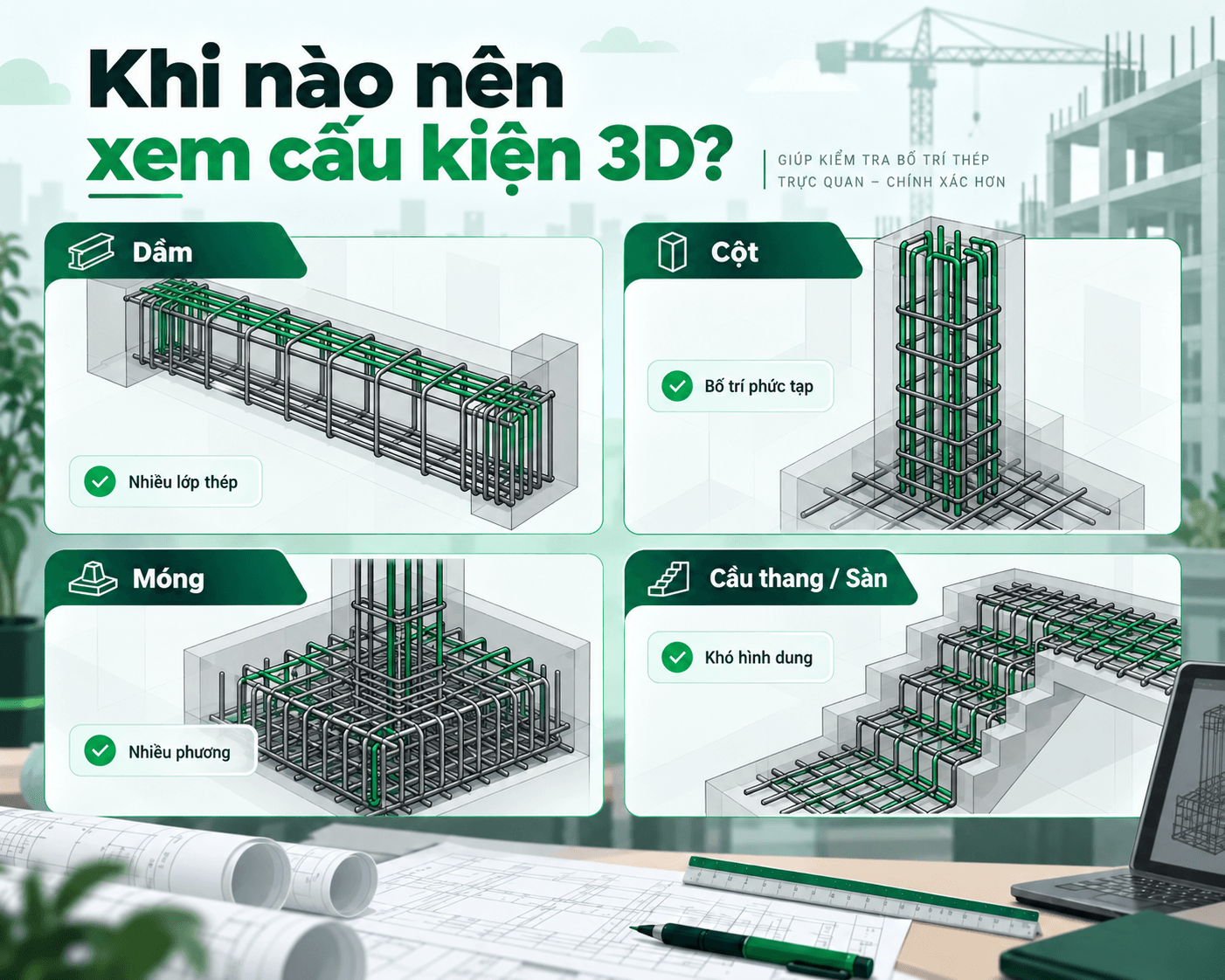
2. Cases where engineers should combine 3D reinforcement checking
Not every component needs to be viewed in 3D. For simple details, 2D drawings can sufficiently meet inspection needs.
However, in areas with complex structures, the 3D view will help engineers better understand how the reinforcement groups are arranged in space.
2.1. Beams with multiple layers of reinforcement and complex configurations
When developing beam shop drawings, engineers must typically check the top bars, bottom bars, reinforcement bars, stirrups, and the anchorage and lap splice positions.
For beams with multiple layers of steel or special shapes, observing only the longitudinal and transverse sections sometimes does not provide a complete view.
3D view supporting engineers:
Observe the correlation between the steel layers.
Visualize the position and shape of the stirrups.
Visually check the layout of reinforcement groups in the beam.
Especially in areas with dense reinforcement, the overall visibility can help engineers quickly identify details that need to be cross-referenced with the technical drawings.
2.2. Columns with dense longitudinal and stirrup reinforcement
For column components, the inspection is not limited to the quantity and diameter of longitudinal steel but also includes the arrangement of stirrups, secondary stirrups, and the spacing between bars.
When observing in 3D, engineers can more easily visualize the relationship between the longitudinal steel system and the stirrups.
This is particularly useful when working with sections that have complex reinforcement structures.
2.3. Foundations with multiple layers of reinforcement in various directions
For foundations, arranging reinforcement in multiple directions and elevations can make the inspection process more complex.
The 3D view helps visually represent the steel layers within the component, thereby assisting engineers in observing the layout sequence and intersection points.
This does not replace checks for anchor length, spacing, or concrete cover, but it makes the information verification process more convenient.
2.4. Floors and stairs with special geometry
For slabs with multiple reinforcement zones or stairs with shapes that change by elevation, visualizing the reinforcement structure from 2D drawings can be labor-intensive.
Observing components in 3D helps engineers better recognize the layout direction, shape, and relationships between groups of steel bars.
As a result, reviewing the overall components before finalizing the drawings becomes more intuitive.
3. What are the benefits of 3D reinforcement checking in the Shop Drawing process?
3.1. Understand reinforcement structures faster
Instead of having to visualize the entire component from multiple cross-sections, engineers can use 3D images to directly observe the layout of the reinforcement groups.
This is particularly useful when approaching a component with many details or when needing to explain the reinforcement layout to others.
The value of 3D lies not only in visually appealing images, but also in helping viewers better understand the structure to be implemented.
3.2. Support for identifying positions that need to be re-checked
When multiple steel bars appear in one space, a 3D view can help identify areas with high reinforcement density or layouts that are difficult to observe on 2D drawings.
From there, engineers can proactively double-check the parameters, positions, and distances between the bars according to the design documents.
It should be noted that viewing components in 3D does not equate to the ability to automatically detect all reinforcement conflicts. Assessments of dimensions, spacing, concrete cover, and technical requirements must still be performed based on accurate data.
3.3. More convenient for communication and drawing review
During the coordination process between engineers, explaining a complex reinforcement detail using only cross-sections is sometimes not intuitive enough.
The 3D view can help all parties visualize the steel layout, identify the positions being discussed, and agree on the contents that need to be adjusted.
As a result, the exchange process has an additional visual tool alongside traditional 2D profiles.
3.4. Support for pre-finalization document review
One of the appropriate times to use a 3D view is after arranging the reinforcement and before finalizing the Shop Drawing.
Overall observation at this stage provides engineers with the opportunity to further review unreasonable details, reducing the risk of detecting issues late when the drawings have already moved to the next steps.
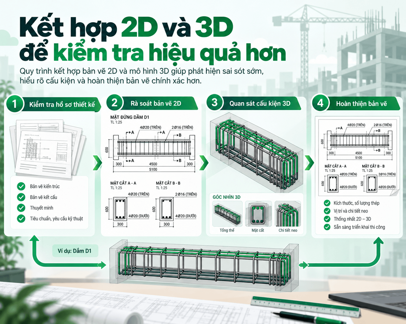
4. How should 2D drawings and 3D views be combined?
Each form of representation has its own strengths. Instead of completely replacing 2D drawings with 3D models, engineers can combine both in a single inspection process.
Step 1: Check data and design requirements
Compare the component dimensions, diameter, quantity, and reinforcement arrangement requirements with the current design documents.
Step 2: Check details on the 2D drawing
Review the cross-sections, anchorage positions, steel bar lengths, spacing, and other important technical specifications.
Step 3: Observe the overall component in 3D form
Use a spatial perspective to view the relationships between reinforcement groups, especially in locations with complex configurations.
Step 4: Cross-check and finalize the drawing
When detecting a location that needs review, go back to check the specifications and design requirements before deciding on an adjustment. Then, review the consistency between the representations and related documents.
This process helps combine the advantages of 2D technical drawings with the visual capabilities of 3D, while keeping professional review at the center.
5. View3D in TakaCAD – Observe 3D components during the deployment process
Recognizing the need for more visual observation and inspection of reinforcement, TakaCAD has added the feature View3D – View 3D components in the October 2026 update.
Instead of only observing components through 2D representations, engineers can view concrete and reinforcement in 3D directly within the deployment window.
The View3D feature supports the following component groups:
Beam: Observe the layout of longitudinal steel, stirrups, and steel groups in the component.
Column: Visualize the longitudinal steel system and stirrups as a space.
Floor: Overall observation of the reinforcement layout of the slab component.
Nails: Visualize the steel layers in the foundation components.
Stairs: Visualize the steel layout according to the shape of the component.
The highlight of View3D is the ability to observe 3D reinforcement directly within the Shop Drawing deployment environment, supporting engineers with visual inspection before finalizing the drawings.
In addition to View3D, TakaCAD also provides tools to support the deployment of reinforcement Shop Drawings for Beams, Slabs, Columns, Foundations, and Stairs, helping to reduce manual tasks in the workflow.
Engineers can learn more about software features and experiences at the official website of __AI_TOK_0__ TakaCADPlease provide the text you would like me to translate.
6. Conclusion: 3D does not replace 2D, but can help with more visual inspection
2D Shop Drawings still play an essential role in representing technical specifications, reinforcement details, and serving the construction process.
However, when components have multiple layers of steel, complex shapes, or intersection points that are difficult to observe, combining a 3D perspective provides an additional useful method of inspection.
2D helps engineers read and compare specifications. 3D helps engineers visualize how the steel bars are arranged together in space.
An effective Shop Drawing process does not necessarily require choosing between these two forms. The important thing is knowing how to leverage the advantages of each method to inspect more thoroughly, limit errors, and finalize drawings that meet construction requirements.
With View3D, TakaCAD aims to help engineers add visual perspectives during the component deployment process, thereby enhancing convenience when checking Shop Drawings.
Experience TakaCAD free for 30 days to explore tools that support the deployment and inspection of reinforcement steel.
Please provide the text you would like me to translate. Learn and try TakaCAD
☎️ Hotline/Zalo support: 0356 719 001