How to read staircase steel drawings: 5 common mistakes when developing Shop Drawings
Stairs are one of the most common components of reinforced concrete structures. However, when starting to develop Shop Drawings, many engineers still encounter difficulties in determining reinforcement directions, arranging steel at landings, or handling connection points.
Unlike components with relatively simple shapes, stairs often combine sloped slab, landing slab, supporting beam and various elevation changesThis means that reading drawings is not just about recognizing steel symbols, but also requires engineers to clearly understand the structure and the connection between components.
So how to read staircase steel reinforcement drawings How to limit confusion during deployment? Let's explore 5 details that require special attention below.
1. Before reading stair reinforcement, what needs to be understood on the drawings?
A set of staircase structural documents typically includes floor plans, sections, and detailed reinforcement layouts. Each type of drawing represents different information, so they must be combined to fully understand the construction.
Staircase plan help determine the location, direction, stair width, landing dimensions, and the relationship with surrounding components.
Staircase cross-section clearly show the shape of the inclined slab, the thickness of the stair slab, step dimensions, elevation, and connection points. This also serves as an important basis for checking the shape and unfolding length of the reinforcement.
Reinforcement layout details provide necessary information regarding diameter, spacing, reinforcement layer position, bar shape, and anchorage and splicing requirements according to the design.
Additionally, the engineer needs to check the general notes of the documents to determine requirements for materials, concrete cover, and detailing regulations.
Important principle: Do not rely on a single projection to deploy all staircase reinforcement. Unclear positions should be cross-referenced with the corresponding sections and design details.
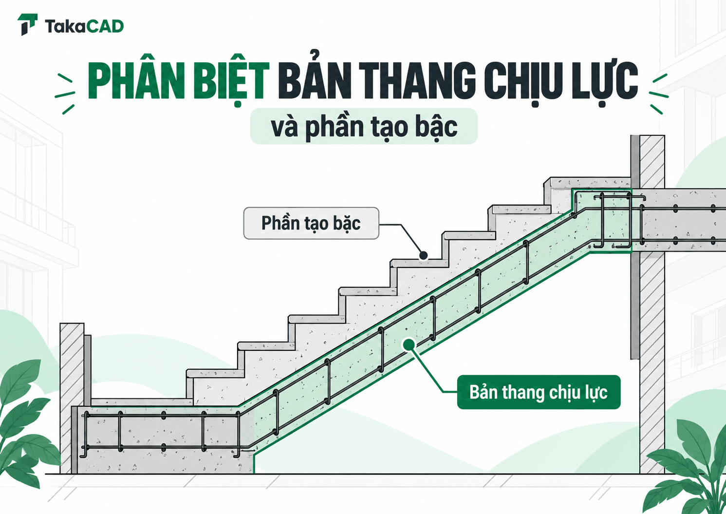
2. Confusion between the load-bearing stringer and the step-creating section
This is one of the most confusing points when reading reinforced concrete staircase cross-sections.
On the cross-section, stairs are usually represented as continuous steps. However, it is necessary to clearly distinguish load-bearing ladder slab with step creation and finishing layers according to the design structure.
The stringer is a load-bearing structural component, while the tread forms the walking surface. Depending on the design and construction method, these parts may be configured differently.
If only observing the zig-zag lines of each step without correctly identifying the position of the bearing slab, engineers may misunderstand the structural thickness or the placement of reinforcement.
How to limit errors:
Before deployment, it is necessary to locate the correct stair slab thickness symbol on the cross-section, distinguish between the structural layers, and check the reinforcement position relative to the structural surface.
In particular, the stair dimensions should not be used to infer the thickness of the load-bearing slab without cross-referencing the design documents.
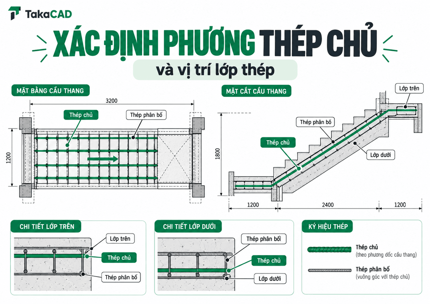
3. Misreading the main steel direction and reinforcement layer position
When reading staircase reinforcement drawings, a common question is: In which direction should the main steel be arranged?
The answer depends on structural diagram and connection method of the stairsPlease provide the text you would like me to translate.
For slabs supported longitudinally, the main reinforcement is typically arranged along the span of the stair slab. Meanwhile, stairs supported along the side edges or those with different structural schemes may require different reinforcement layouts.
Therefore, it cannot be assumed by default that all stairs have the same main steel direction.
In addition to the steel layout, engineers must also pay attention to the positions of the top and bottom layers.
In some structural diagrams, the mid-span region and the region near the supports have different reinforcement requirements. If one only observes the plan view and ignores the cross-sectional details, the determination of reinforcement placement may be inaccurate.
For example, symbol Ø12a150 Specify that the steel bars have a diameter of 12 mm, arranged at a spacing of 150 mm according to the drawing instructions.
However, simply being able to read this symbol is not enough. The engineer needs to determine the direction of the steel bar, its layer, and the extent of its arrangement.
Note: The load-bearing direction, steel layer, diameter, and spacing must be determined from the design documents. Do not arbitrarily change the arrangement plan based on experience from another project.
4. Omit the connection details between the stair flight and the landing
If the scale is the easily recognizable part, then the junction between the stair flight and the landing another area that needs closer observation.
Here, the structural shape transitions from an inclined slab to a horizontal slab. Simultaneously, depending on the design scheme, this area may involve force transmission between the stair slab, landing, and supporting beams.
Information that requires special attention includes the position of the bearing pads, the reinforcement layout at the junction areas, the bending shapes, and the anchorage lengths of the steel bars.
A possible error is that the implementation engineer treats the stair plates and landing plates as two completely independent groups without checking the connection requirements between them.
Conversely, arbitrarily extending or splicing steel bars across junction positions when the drawings do not provide instructions can also lead to discrepancies from the design.
How to check effectiveness:
Compare the cross-section passing through the landing area with the corresponding steel details. Observe the positions where the steel bars start, end, bend, or are anchored into other components.
If the drawings lack information on connection anchors or show inconsistencies, the engineer must clarify them with the design department before finalizing the Shop Drawings.
This is an important step to avoid multiple adjustments when the drawings are reviewed or implemented on-site.
5. Incorrect dimensions and elevations when deploying stair reinforcement drawings
Stairs are inclined components, so distinguishing between the plan dimension and the dimension along the slope is very important.
On the floor plan, engineers typically observe the projected length of the stair flight. However, when deploying a steel bar along the sloped slab, the actual dimension of this bar segment cannot simply be taken as the projected length.
If the wrong size is used as the basis for determining the shape of the steel bar, the processing length may be affected.
Similarly, failing to check the elevation of the stair head, landings, and the end point of the stair flight can lead to geometric discrepancies during implementation.
To limit this situation, engineers need to clearly distinguish between the horizontal dimension, the dimension along the slope, and the actual deployment length of the steel bar.
The final machining length must also consider the bending shape, anchorage positions, concrete cover, and other design requirements.
Especially for stairs with multiple flights or complex changes in elevation, cross-checking the geometry between sections is a step that should not be overlooked.
6. Omitting steel details when summarizing and exporting drawings
After completing the reinforcement layout, many engineers tend to move immediately to quantity take-off.
However, the fact that the drawing correctly represents the overall shape does not mean that all rebar information has been fully verified.
Some common scenarios include a lack of additional steel at connection points, incorrect bar marks between stair flights, or inaccurate quantity take-offs due to incorrectly defined layout ranges.
For example, two steel bars with the same diameter but different bending shapes or lengths may not necessarily be able to share the same statistical code.
Therefore, before exporting the statistics table, it is necessary to check the consistency between the symbols on the drawing, the shape of the steel bars, the quantity, and the processing length.
Especially for components with many bent bars, checking the actual shape will help engineers identify inconsistencies that are difficult to detect by only looking at the bill of quantities.

7. Inspection process for staircase shop drawings before finalization
To limit common errors, engineers can apply a short checklist before publishing drawings:
Geometry check: Cross-check the dimensions of the stairs, steps, landings, and elevations between the floor plan and the section.
Check reinforcement layout: Confirm the main steel bars, steel layer, diameter, spacing, and layout range.
Check links: Review the steel at the knee area, the junction between the stair slab and the landing, and the anchorage and splicing requirements.
Check machining details: Compare the bending shape, length, and steel bar code with the design.
Statistical check: Ensure the quantity, symbols, and volume of reinforcement are consistent with the Shop Drawings.
A clear checking process not only helps reduce the risk of overlooking details but also facilitates the process when drawings need to be updated according to changes in the design documents.
8. Deploying staircase Shop Drawings more conveniently with TakaCAD
During the Shop Drawing deployment process, engineers often have to perform multiple steps such as reading structural data, arranging reinforcement, detailing, and calculating quantities.
When these tasks are performed entirely manually, adjusting or updating data can cause engineers to spend additional time on operations.
TakaCAD is software that supports the implementation of reinforcement Shop Drawings, including staircase and landing components.
With tools supporting drawing deployment and reinforcement statistics, TakaCAD helps engineers reduce repetitive tasks while working in the CAD environment.
Instead of spending too much time on drawing construction and presentation steps, engineers can focus more on checking parameters, cross-referencing reinforcement details, and finalizing the documentation.
However, despite using supporting software, checking for consistency with the approved design profile remains a necessary step before releasing the drawings.
Want to experience the Shop Drawing deployment process with TakaCAD?
Explore the reinforcement deployment tools for Beams – Slabs – Columns/Walls – Foundations – Stairs and experience the software directly on actual drawings.
Please provide the text you would like me to translate. Try TakaCAD for free for 30 days
💬 Consulting support: 0356 719 001
9. Frequently asked questions when reading staircase steel drawings
The main reinforcement of the stairs always runs along the length of the stair slab, right?
Not entirely. The direction of the main reinforcement depends on the load-bearing diagram, the position of the supports, and the design plan. For some types of stairs, the main reinforcement may be arranged in a different direction.
Is it possible to determine the length of staircase steel from the floor plan alone?
It is not recommended. It is necessary to cross-reference sections and reinforcement details to determine the actual geometry, especially for bars running along sloped slabs or those with bends and anchors into other components.
How to handle it when the stair floor plan and section drawings are inconsistent?
Engineers need to check the document version, design notes, and related details. If contradictions still exist, a request for design clarification must be made instead of arbitrarily selecting dimensions or reinforcement layouts.
Conclusion
Reading staircase reinforcement drawings correctly is a crucial step for accurate Shop Drawing implementation and minimizing future revisions.
From distinguishing the load-bearing slab and determining the main steel direction to checking connection positions and fabrication lengths, every detail plays a role in completing the shop drawings for construction.
The important thing is not just deploying drawings quickly, but also clearly understanding the construction, verifying the design information correctly, and building a consistent workflow.
Combining professional expertise with support tools such as TakaCAD will help engineers further optimize the process of implementing reinforcement Shop Drawings in practice.